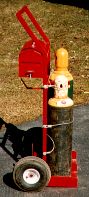
How to Make a Welding Cart
You may be wondering why I built a torch cart when they are available at fairly affordable prices.(If you count my time & material I have much more invested than a commercial one would cost) I simply could not find one that possessed the features I wanted. I have a habit of overbuilding things, for which I am sometimes criticized. I feel much better knowing it`s a little tougher than it needs to be. While it is more time consuming, I feel it is well worth the added expense & effort. My time is very valuable to me, but I think it`s time well spent.
So for all these reasons I set out to build a torch cart I would be happy with. Prior to needing a torch cart, I needed a hand truck. Again I could not find what I wanted so I built one. I wanted the torch cart to match the hand truck. I am very picky about things like that, I like everything to look professional when I`m done.
This cart is a combination of all the carts I`ve seen in welding books, magazines, tool books and welding shops. I do not pretend to be the originator of the “torch cart”. I simply gathered all the features that appealed to me and did away with what I did not like.
I must warn you that I am not a draftsman or a writer. I am trying to find a fast, easy to use CAD program to help with projects like this.(any suggestions?) You will probably find lots of spelling and grammar mistakes, please ignore them.
I will also tell you that I do the majority of my projects like this with nothing more than a couple sketches and some notes and measurements scribbled down on a piece of paper. I do not make any drawings, or any type of formal notes. I keep telling myself I will in the future, make drawings & keep notes. It just seems I never get around to it & before you know it the project is done. So you may see that I jump around a lot and repeat myself, please forgive me. This cart may not appeal to you. Your needs may differ from mine, so you may wish to add or delete some features, or change them. Here is a list of other features to consider when building.
Most people substitute the tool box for an open tray. True this speeds the retrieval of an item, it`s also a gathering place for dirt, grinding dust, etc.

Some people weld pieces of 2″ pipe in a vertical position to the cart for rod storage. I`m personally not in favor of this because the flux seems to take a beating & gets bashed off. Also, I like to store the rod in the house to keep moisture to a minimum & prevent contamination.
Another feature I did not like was the traditional chain restraint setup. I feel the cable/turnbuckle system is superior due to its adjustability. I`ve never seen this setup before, but I`m not saying it is not out there. I feel it holds the tanks better with less movement. With the chain, it never seems tight enough. I know the tanks won`t fall over, but I don`t like them banging around at all.
Now some things that need an explanation. I added the middle tank holding bar because I acquired a set of smaller tanks. This is why this bar is bolted in place. The cart was already painted & I did not want to go through the trouble of cleaning the paint off, welding the bar in place, then repainting it. It`s much faster and easier to weld it in place, and it looks a lot nicer. I show that cross member “G”, 2nd from the bottom, with holes going through the tubing “A” & into “G”. The bolts that hold the cable in place also hold the cross member in place. Again, if you think you will use small tanks, weld that one in like the others. It will look much better.
I also strongly recommend the pneumatic tire/wheel combo. I can easily roll around in the shop or out in the yard. They came from Northern Hydraulics, I`m not sure of the part number, but list the size on the material list.
I added a hook to hang the torch on so you`re not laying it on the hoses. The reason mine is bolted on instead of welded on is because I built the cart before I purchased the torch.
Materials Required for the Cart
PARTS & MATERIAL LIST
- Uprights (2) HR 1x1x11Ga. Square Tube
- Base Plate (1) HR plate
- Handle (1) 3/4 Black Iron Pipe with ends welded shut (refer to text)
- Side Plates (2) HR 1/4×3 Flat Stock
- Base Divider (1) HR 1/4×3 Flat Stock
- Mid & Top Dividers (2) HR 1/4×1 Flat Stock
- Upright Cross members (4) HR 1x1x11Ga. Square Tube
- Tool Box Brackets (2) HR 1/8x1x1 Angle Iron (depends on your toolbox)
- Hose Rack (1) HR 1/8x 1 « Flat Stock (will depend on length of hose)
- Cap Holders (2) HR 1/8×1 « Flat Stock
- * Axle Tube (1) 3/4 Black Iron Pipe
- * Axle (1) CRS 3/4 Diameter
- * Axle Support Brackets (2) HR
- Torch Hook (1) CRS
- Toll Box Hold Down Tabs (2) HR 1/4×1 Flat Stock
- Tool Box Tabs (2) HR 1/8×1 « x1 « Angle Iron
* The dimensions of these parts depend upon your choice of axle dia.& tire/wheel combo, if not the same as mine you must make to suit your parts.
2 5/16 Clevis Pins 1 1/4 long
2 3/32 Hairpin Clips to fit Clevis Pins
1 Toolbox-Service Star Hardware 19Lx6Wx6″ H
2 Tires/Wheels “Deli Tire” Tubeless 4.10/3.50-4 2P.R. Load Range A
2 3/16 Cables (vinyl coated) for large cylinders (make to fit as per text)
1 3/16 Cable (vinyl coated) for smaller size cylinders (make to fit as per text)
6 Cable Ferrules
3 Turnbuckles-Service Star Hardware 1/4-20 Thread,3″ body length, closed eye on one end
2 3/4 Flat Washers (depends on your axle size)
6 3/8-24×1 Hex Head Bolts
6 3/8 Flat Washers
2 1/8×1 Cotter Pins
Note: About the tool box mounting method, you might want to make brackets H longer with a stop on the end. This would prevent you from having to undo clips to remove box, or to gain access to under tray storage area. I have not found it to be a real problem yet, if I do I`ll change it.
All measurements are in inches, unless specified otherwise
The radius on parts are optional, unless specified otherwise
Construction
Lets start construction now. I started with the uprights, (see assembly drawing 1) Cut to length, then layout the angle & with a jigsaw or sawzall, cut a pie shaped piece out of the tubing and bend the joint together. I then weld the 3 sides of the joint. I ground down the welds on 2 sides and left the inner weld, for a smooth appearance. Be sure of your welds before doing this. Then do the same for the other upright.
Next, cut your base plate, B to size and grind the edges smooth. Then weld the uprights to the base plate keeping everything square.(Tack weld first) I then tacked the cross members G (see assembly drawing 2,4) in the positions marked. I don`t show G on the drawings, it`s just a piece of tubing cut to length.
Now cut your handle C (see assembly drawing 2,3) to length, take measurements along the way in case your dimensions differ from mine for some reason. I then welded the end shut using a piece of 3/4″ stock to fill up the hole. After welding I faced them in the lathe. After doing this you can tack weld the handle in place.
Next tack weld the side plates D in place, then the base divider E. At this time you can weld the mid & top dividers F in place. You can weld up all the joints now if you haven`t already. Again, I grind down certain welds to lend to the appearance, you don`t have to.
You can now weld on your torch hook N (see assembly drawing 2). Make the hook to fit your torch. I used a piece of 1″ diam. stock to form the loop. Now your hose rack I – I , and your tool box brackets H, (Also making sure your box fits this space and is where you want it) and also weld the toolbox hold down tabs O (see assembly drawing 1) in position.
Now layout and cut the axle support brackets M, drill your axle hole and tack them in place. (These measurements are for my tire/wheel combo, make your brackets fit your combo.) Cut your axle L (cut it longer to fit it in place), and your axle tube K.
Now set your axle tube in place, and put your axle in place, put on a tire flat washer and mark your axle for the cotter pin hole on each side of the axle. This is to insure your axle will be set up properly incase your parts are different from mine.
I Placed a piece of 3/8″ thick stock under the back or the base plate and set each wheel in place and ran the axle through each support and axle tube to keep things in line. Remember that all these measurements are for my tire/wheel combo. You`ll have to set it up for your combination. When things were in order, and I was satisfied, I tack welded the axle supports M in place. My supports are flush with the outer surface of the uprights A . I welded them inside and out, then ground down the outer welds smooth. Make certain that you check to see if the cart pulls back without the base plate hitting the ground.(This was the reason for the 3/8″ shim under the back).
Now take the assembly apart and drill your cotter pin holes and debbur. Also, drill a 1/2″ hole on each end of your axle tube, this is to plug weld the axle to the tube so the axle does not spin. My wheels have bearings in them.
You can mow reassemble everything and install your cotter pins and make sure everything is ok. When everything is acceptable, tack weld your axle tube to support brackets M. Take your tires off and spray the protruding axles with anti-splatter spray to protect them. Then weld your tube in place, and finish plug welding axle to tube. I ground down the plug welds for a better appearance also.
Weld your supports at this time if you haven`t already. Finish the welds (grind) if you so desire. Then weld the cap holders J in place, there location is not critical. Mine are about 2″ in from the outer face of A . Hold a cap in place and make sure it does not interfere with anything.
Next layout, drill and tap your 3/8-24 holes for your cable bolts. Make up your cables to fit your tanks using the cable ferrules. Place a ferrule on cable, make a loop that your bolt will fit through and hammer ferrule tight. Now bolt this end to the cart. Then stretch the cable to the other side (with tank in place, and with the turnbuckle in place and extended). Now form a loop that will fit over the hook of the turnbuckle and mark the cable with a magic marker so you know where to place the cable. Next, place a ferrule on cable and loop cable back through ferrule to line it up with your mark and hammer like the other end.
I think the correct method is actually to press the ferrule in a fixture to lock them in place. I`ve had good luck using a hammer, don`t get crazy with the hammer. DO NOT MAKE CABLES UP THIS WAY AND USE THEM FOR LIFTING !! This is basically how I determined cable length. I made up cables for both large and small tanks. I also bent the closed eye portion of the turnbuckle in slightly (30 deg. + or -).
After all the cables are done you can now bolt the 2 brackets P to tool box. You are going to have to make all this fit your application. These dimensions are for what I used. I can open my toolbox enough to get my goggles and frequently used items out without taking the box off. After tabs P are bolted to box mark a hole using a transfer punch in O. Remove box and drill a clearance hole for a 5/16 clevis pins and dauber.
Assembly Information
Assembly Drawing 1 – Assembly Drawing 2 – Assembly Drawing 3 – Assembly Drawing 4
Finishing
After all the welding and grinding is done I go over the entire cart with a file and sandpaper. Remove all rough edges and blend all joints if desired. Now wipe the cart down with wax and grease remover, prime and paint. When it`s good and dry you can assemble the cart and set it up how you want.
I hope this article is of value to somebody. This is my first attempt at doing an article. I hope you could follow everything ok, and that I did not leave anything out. If you have any comments or advice about my article please let me know. It was a lot of work to write up the article and do the “drawings” after doing the cart.(About 2 years after building it.)
I hope this was enjoyable for you. Any comments about the article, or CAD programs, or advice on writing future columns, can be sent to:
Construction
Lets start construction now. I started with the uprights, (see assembly drawing 1) Cut to length, then layout the angle & with a jigsaw or sawzall, cut a pie shaped piece out of the tubing and bend the joint together. I then weld the 3 sides of the joint. I ground down the welds on 2 sides and left the inner weld, for a smooth appearance. Be sure of your welds before doing this. Then do the same for the other upright.
Next, cut your base plate, B to size and grind the edges smooth. Then weld the uprights to the base plate keeping everything square.(Tack weld first) I then tacked the cross members G (see assembly drawing 2,4) in the positions marked. I don’t show G on the drawings, it’s just a piece of tubing cut to length.
Now cut your handle C (see assembly drawing 2,3) to length, take measurements along the way in case your dimensions differ from mine for some reason. I then welded the end shut using a piece of 3/4″ stock to fill up the hole. After welding I faced them in the lathe. After doing this you can tack weld the handle in place.
Next tack weld the side plates D in place, then the base divider E. At this time you can weld the mid & top dividers F in place. You can weld up all the joints now if you haven’t already. Again, I grind down certain welds to lend to the appearance, you don’t have to.
You can now weld on your torch hook N (see assembly drawing 2). Make the hook to fit your torch. I used a piece of 1″ diam. stock to form the loop. Now your hose rack I – I , and your tool box brackets H, (Also making sure your box fits this space and is where you want it) and also weld the toolbox hold down tabs O (see assembly drawing 1) in position.
Now layout and cut the axle support brackets M, drill your axle hole and tack them in place. (These measurements are for my tire/wheel combo, make your brackets fit your combo.) Cut your axle L (cut it longer to fit it in place), and your axle tube K.
Now set your axle tube in place, and put your axle in place, put on a tire flat washer and mark your axle for the cotter pin hole on each side of the axle. This is to insure your axle will be set up properly incase your parts are different from mine.
I Placed a piece of 3/8″ thick stock under the back or the base plate and set each wheel in place and ran the axle through each support and axle tube to keep things in line. Remember that all these measurements are for my tire/wheel combo. You`ll have to set it up for your combination. When things were in order, and I was satisfied, I tack welded the axle supports M in place. My supports are flush with the outer surface of the uprights A . I welded them inside and out, then ground down the outer welds smooth. Make certain that you check to see if the cart pulls back without the base plate hitting the ground.(This was the reason for the 3/8″ shim under the back).
Now take the assembly apart and drill your cotter pin holes and debbur. Also, drill a 1/2″ hole on each end of your axle tube, this is to plug weld the axle to the tube so the axle does not spin. My wheels have bearings in them.
You can mow reassemble everything and install your cotter pins and make sure everything is ok. When everything is acceptable, tack weld your axle tube to support brackets M. Take your tires off and spray the protruding axles with anti-splatter spray to protect them. Then weld your tube in place, and finish plug welding axle to tube. I ground down the plug welds for a better appearance also.
Weld your supports at this time if you haven`t already. Finish the welds (grind) if you so desire. Then weld the cap holders J in place, there location is not critical. Mine are about 2″ in from the outer face of A . Hold a cap in place and make sure it does not interfere with anything.
Next layout, drill and tap your 3/8-24 holes for your cable bolts. Make up your cables to fit your tanks using the cable ferrules. Place a ferrule on cable, make a loop that your bolt will fit through and hammer ferrule tight. Now bolt this end to the cart. Then stretch the cable to the other side (with tank in place, and with the turnbuckle in place and extended). Now form a loop that will fit over the hook of the turnbuckle and mark the cable with a magic marker so you know where to place the cable. Next, place a ferrule on cable and loop cable back through ferrule to line it up with your mark and hammer like the other end.
I think the correct method is actually to press the ferrule in a fixture to lock them in place. I’ve had good luck using a hammer, don’t get crazy with the hammer. DO NOT MAKE CABLES UP THIS WAY AND USE THEM FOR LIFTING !! This is basically how I determined cable length. I made up cables for both large and small tanks. I also bent the closed eye portion of the turnbuckle in slightly (30 deg. + or -).
After all the cables are done you can now bolt the 2 brackets P to tool box. You are going to have to make all this fit your application. These dimensions are for what I used. I can open my toolbox enough to get my goggles and frequently used items out without taking the box off. After tabs P are bolted to box mark a hole using a transfer punch in O. Remove box and drill a clearance hole for a 5/16 clevis pins and dauber.
Assembly Information
Assembly Drawing 1 – Assembly Drawing 2 – Assembly Drawing 3 – Assembly Drawing 4
Finishing
After all the welding and grinding is done I go over the entire cart with a file and sandpaper. Remove all rough edges and blend all joints if desired. Now wipe the cart down with wax and grease remover, prime and paint. When it`s good and dry you can assemble the cart and set it up how you want.
I hope this article is of value to somebody. This is my first attempt at doing an article. I hope you could follow everything ok, and that I did not leave anything out. If you have any comments or advice about my article please let me know. It was a lot of work to write up the article and do the “drawings” after doing the cart.(About 2 years after building it.)
I hope this was enjoyable for you. Any comments about the article, or CAD programs, or advice on writing future columns, can be sent to:
Email: Craig Suslosky