Background
Most modern lathes incorporate a secondary gear reduction into their design to allow the user to select the speed required for part being machined. In some designs like those from South Bend and Myford, the reducing gear is located under the headstock cover on the rear of the lathe – thus the name “backgear”. In these designs, this portion of the gear-train is manually shifted into place using a lever and locking mechanism.
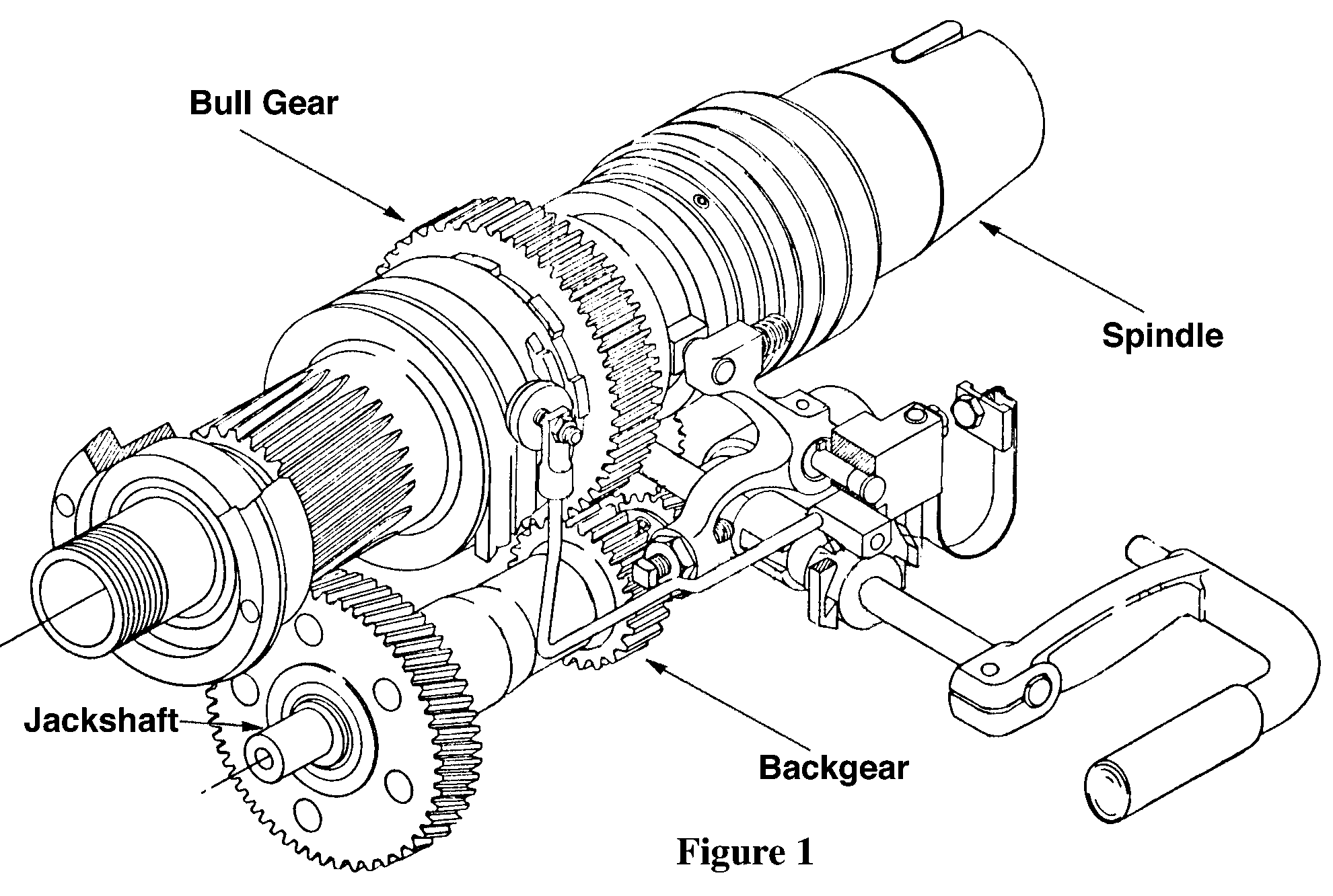
The Delta Backgear and Shifting Mechanism
Several years ago, I purchased a used Rockwell/Delta 11″ lathe, c.1965, from a private party. This machine had been used in a tool and die business in the midwest.
The Delta lathe uses a simple, compact design where the backgear and shifting mechanism is located under the headstock. This arrangement provides for disengaging the clutch between the drive shaft and the headstock, and simultaneously engaging the backgear on a separate jack-shaft.
This back gear is a single-piece casting machined with two gears – a 100T bevel gear that engages with the drive shaft and a 35T spur gear that transfers the power to a bull gear on the headstock. This arrangement provides a 12 to 1 reduction in speed at the headstock. The casting is bored for two bronze bushings and the assembly rides freely on the jackshaft. A schematic drawing of the arrangement is shown in figure 1.
Figure 1Damage to the Gear
While making some heavy cuts in steel, the backgear failed causing the headstock to jam. After removing the headstock from the lathe bed and removing the gear/shaft assembly, it was apparent this was not the first time such a problem had occurred. In fact I found three teeth on the smaller, spur gear had previously broken off and had been welded back to the shaft. I had broken two of the three welded teeth plus an adjacent tooth.
Fortunately the bull-gear on the headstock was not seriously damaged. It had a couple of minor chips from its past life, but this newest incident had not further damaged the gear. A call to Delta confirmed my worst fear that replacement parts were no longer available.
Measurement of the Gear
There ensued a round of measurements to determine the specifications of the original gear. The number of teeth and pitch diameter were obvious (35-T, 16-DP), but measurements to confirm the pressure angle were indirect at best. At first, I assumed the gear used the currently popular 14 1/2 degree pressure angle. It seemed to mesh with a Boston 16-DP, 14 1/2 degree change-gear. But Jon Anderson, an experienced machinist, noted a small amount of roughness indicating that tip of the new Boston gear was striking the flanks of the Delta gear.
After careful study of the articles in the Machinery’s Handbook, ed. 22, a set of thread wires were used to measure and compare pitch diameter of the actual gear to that specified for 14 1/2 degree and the older 20 degree gear designs. It became clear that the gear manufactured by Delta was closer to 20 degree pressure angle. I say “closer”, because it was not precisely within the specified tolerances on all measurements. (It is not clear whether the differences were due to measurement errors, wear on the old gear, or the possibility that Delta had used a re-ground gear cutter that was out of tolerance.)
Solutions Considered
Considerable commentary and many excellent suggestions were offered when I requested opinions from the members of the CompuServe Handcrafts Metalworking forum. Their suggestions can be broken down into three general methods.
Re-weld or braze the old teeth on the damaged shaft.
Weld or braze an insert and reshape it to the correct profile.
Replace the spur gear with a ring gear.
After seeing that the teeth had already been welded once, that pretty much eliminated any method that welded or brazed the teeth back on the shaft. It seemed clear that if that method had failed once, it was bound to fail again.
Method of Repair
What was left was totally replacing the spur gear. Jon Anderson agreed to make a new gear and we selected Gray Cast Iron, Class 40, from Metal Buyers Mart. This a continuous cast, close grain, uniform material that has excellent machining qualities. We had MBM cut two, 1″ thick slabs, 3″ in diameter.
There was a trade-off between leaving the shaft as large in diameter as possible vs. retaining enough material between the internal bore and the root of the new gear teeth as to not weaken the ring gear. Based on the material available, it was decided that the nominal diameter should be 1.625″. A cross-section of the gear and shaft is shown in figure 2.
Figure 2
We had several options of how to attach the ring gear to the existing casting.
The gear could be press-fit to the shaft, but cast iron is notoriously weak in tension.
The assembly could be brazed together, but the press-fit bronze bearings would not likely survive the heat.
The gear could be attached using Loctite.
After studying the manufacturer’s specifications, I decided that Loctite would be ideal. There would be no undue stress to the cast iron, nor any heating of the parts to brazing temperatures. This application puts the bond line in shear which is precisely what Loctite is designed to accommodate. Loctite recommends RC/680, high strength, bonding compound for this application.
The original gear was placed on a shaft that was turned to size between centers on the Delta lathe. This assured that the newly machined shaft would be concentric with the jackshaft.
Turning down the old, damaged gear proved to be more difficult than anticipated. It appeared that over the years, the teeth of the old gear had become work-hardened. The old Delta part machined very poorly until I got below the root of the original gear and into the base material. At that point it machined as you would expect from a cast iron product.
Loctite recommends no more than 0.015″ of radial slop in the mating parts. I allowed just over 0.002″ difference in diameter. They do not recommend a surface treatment for the parts in this application, but I made sure they were very clean and dry. Final cleaning was with 90% isopropyl alcohol to remove traces of water from the surfaces.
The Loctite RC/680 completely wet the mating surfaces and I quickly put them together. They immediately bonded in place – i.e. there was no room for second thoughts.
Conclusions
After letting the gear assembly cure for the recommended 24 hours, the lathe was reassembled. Considerable care was taken to assure the new gear meshed correctly with the existing drive and bull gears in the headstock. After a fresh coating of grease on the gears, the lathe was put back in service.
The new gear runs very smoothly – much better that before. I attribute most of this to the careful machining done on the ring gear by Jon Anderson. The Loctite has proven its strength during several, heavy test cuts in both aluminum and stainless steel. Even under harsh conditions, the gear appears to be functioning as well or better than the original part.
Author: Roger Peterson