Once you own a stationary belt sander, it’s hard to imagine life without one. Clamped to a bench in your shop, these workhorses deburr, contour, polish, grind and shape almost any type of material. Great for the woodworking shop as well as the metalworking shop.
One of my addictions in life draws me to garage sales, estate sales, flea markets, etc looking for a treasured piece (junk) for my shop. Almost always, when I find an old motor, I pick it up. Rarely paying more than $10 or so, I’m hardly making a dent in my savings accounts. Pretty thrifty!
The purpose of this site is to demonstrate a very simple belt sander that can be made from an old motor very quickly in your shop. I encourage you to use as much “local resource” as possible. By local resources, I mean any old junk you’ve already got laying around. If I say “use 3/4″ plywood” but you’ve got 5/8….then use what you’ve got! These machines are so simple that you really won’t need to measure much when building them. If it looks right, it probably is.
A quick note about safety
The photos shown here are the way I do things in my shop. I’m not implying that they are safe! You must decide what is safe and you must work within your own capabilities. If you’re not comfortable with anything shown here, don’t try it.
Getting started
I’ve reduced the full size plans and placed it here. I apologize for the small size.
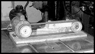
Referring to the plans above; note the 4 main components to this belt sander.
- The motor with the driver roller (on left)
- The belt support (between rollers)
- The idler roller and bracket ( on the right)
- The base plate
This is the basis and order of construction.
Motors

The type of motor that you use will be limited only by your imagination. Generally bigger is better. I like a 1/4hp 1725 rpm, it’s a popular size and I seem to find more of them than any other type. A 3450 rpm also works excellent and if you use one, you’ll need more hp, like 1/2hp. The 1/2hp 3450 rpm will give the same torque as the 1/4hp 1725rpm motor but deliver it twice as fast. Since hp =torque x speed, if you double the speed….you need to double the hp to keep the same torque, and torque is what keeps the belt moving.
The best choice frame would be a totally enclosed frame, simply to keep out dust. (TEFC…Totally Enclosed Fan Cooled, TENV…Totally Enclosed NonVentilated) However, if your “local resources” yield an open frame motor for the right price use it. To reduce dust ingestion in an open motor, I simply run the belt direction away from the motor. Also a dust collector/shop vac is recommended when sanding. If you breath dust then your motor is breathing dust!
Some motors are reversible, while others are not. If your motor is not reversible, take a minute to see which way it turns. Looking at the end of the output shaft, if it turns clockwise, you can build to the drawing. If it turns counterclockwise, then you should build a mirror image of the drawing.
For reference, the motor used on this sander is 1/4 hp 1725 rpm and has plenty of power.
Rollers

Since the rollers are the most difficult item to acquire, I designed these and produce them. They are available at:Beaumont Metals. See link at end of this article
Created from machined aluminum castings, the driver roller is available for either a 1/2″ or 5/8″ motor shaft.
The idler roller is press fitted with 2 sealed bearings and fits nicely on a 1/2″ bolt.
Building the frame
First, I rough out some 3/4″ plywood for the base plate, the belt support, and the idler roller bracket.
The base plate was cut to 10″ x 24″ and set aside.
The belt support and idler roller bracket were made in one piece, then separated as one of the last steps. They both fasten to the base plate and are located by a key. The idler roller bracket slides on the key to adjust the belt tension.
Cut out a couple of gussets about 2 1/2 X 5 and set aside. On a 9″ X 12″ sheet of 3/4 ply, cut two dados the same width as the gussets.

Note the triangle drawn on the face of the board. This helps figure out the orientation of the parts after they are cut apart.
Rip the board into two pieces about 3 1/4 X 12, and 5 1/4 X 12. Don’t get hung up on exact sizes here, I just made everything oversized so that I could cut it exact after glue up.

I used a butt joint with biscuits, but use whatever your comfortable with.

After dry fitting, I glued and clamped everything up.

When the glue dried, I cut everything to size at 4 3/4″ high X 3″ wide.

Then beveled the gussets.

With the miter gauge on the table saw, I separated the idler roller bracket from the belt support.

The slot in the idler roller bracket must be sufficiently long to provide enough travel to tighten the belt. Since I had a 1/4″ carriage bolt for the fastener, I made the slot by first drilling several holes with a 1/4″ drill bit.

Then chopped out the waste with a chisel.

The finished slot, down and dirty.

The keyway was cut in the idler roller bracket and the belt support using a dado. I then milled the keyway in the base plate. Since there is nothing very critical about the size of the key, feel free to change it so you may use something on hand. Instead of using a dado, you could use a router.

Assembly
From here we can start to assemble everything. First, I placed the components on the base board to be sure that I had plenty of adjustment for the belt tension. Then spotted the holes for drilling. I used a mixture of blind nuts and carriage bolts because I had them on hand. Again, use whatever you’ve got!
The base plate was counterbored on the bottom to relieve the fasteners as shown.

After notching the belt support and rounding the idler bracket, they were assembled to the base plate.

The idler roller slips over a piece of 1/2″ threaded rod which is bolted to the bracket. Large washers help to stiffen the joint.

After adding the motor, tighten the belt, and complete the belt support by fastening the shelf which the belt rides on. I used 3 drywall screws, but an alternative might be biscuits and glue.

A residential light switch and enclosure was mounted. Make sure the switch is rated to handle the motor current. At 110V, a 15A switch is good up to about 1hp.

Adjusting the tracking
Don’t let the tracking frustrate you! If your machine doesn’t track perfect at start up, congratulations, it’s just like all of mine. Granted that every thing is reasonably rigid and aligned and the belt is some tension, the belt will not wander due to the crowned rollers. However, initially the belt may not track in the center of the rollers. This is easily corrected by loosening the motor and toe-in or tow-out the rollers. Frustration is usually due to over compensation. A little adjustment goes a long way here.
I’ve had several questions about “how much tension”. I usually tighten the belt just past the point where it stops slapping, which is not very tight! But it’ll have to be tight enough so it won’t slip. You’ll quickly learn.
Operation

Ahhhh! Now that it’s completed, notice the designed features.
In front of the partial length belt support (just down stream from the motor) is an area for “free-form” sanding. The belt support was notched out to provide clearance. Basically, the belt is unsupported. Free form sanding is great for polishing and shaping where the belt is allowed to follow the contour of the work piece. Note the belt deflection.

It is important that this “free form” area be located on the exit side of a roller otherwise the belt tracking will be upset and the belt may be thrown off. In this case, the belt support stabilizes the belt as it starts over the idler.
Down stream from the “free-form area”, the belt rides on the belt support block. This area sands pieces flat. Great for leveling, deburring and beveling…..in the photo on the left, I’m sanding the handle flush with the top of the mallet head.

The work piece can also be sanded against the rollers. This shot demonstrates the capabilities of the 1/4hp 1725rpm motor. It has has power to spare… even during heavy grinding!
To conclude: I hope that you enjoyed this posting and that perhaps you will build one of these fantastic machines. My goal was to demonstrate the simplicity of this design and since I’m not “the sharpest knife in the drawer” I’m sure that many people can find ways to improve it. I would like to encourage you.
If you build it,…. have fun and feel free to drop me a line if you have any questions or comments.