This document is a compilation of notes, observations and modifications I did while making the Tinker T&C; grinder attachment. Complete plans, as well as the 2 castings, are available through Guy Lautard.Com. The easiest way to run through this is by following the “suggested order of construction” table on Page IV of the published instructions. I’ll take the items one at a time from top to bottom. This report isn’t any kind of endorsement of anything or anyone, it’s just a bunch of notes of how I did something. Feel free to use or ignore any or all of it, and don’t come to me if you hurt yourself.
The toothrest bracket and finger (parts 14 and 15) are pretty simple…no changes were made here.
The thumbwheel and screw, part 18, is all one piece. The threaded end has a .032 slot cut in it .25” deep for a piece of plastic that will add friction and keep the screw from turning on it’s own. Kind of like a home-made Nyloc screw. The alternative is to make another thumbwheel, threaded through, to act as a locknut. Or the slot can be slightly spread to increase the friction.
The key, spring, and thumbscrew are as follows: The key (21) is as per the plans. The spring (5) is a spring from a ball point pen epoxied into the key. Easier than winding and heat treating one tiny little spring. Thumbscrew (19) is like the other 2 (see below, parts 11 and 22), only with a 7/32 hole .25 deep.
Thumbscrews (11 & 22). These are made from 1” diameter brass stock and steel rod threaded 5/16-24. The brass was knurled, drilled, tapped 5/16-24, and cut to length. The steel was screwed in, to length, then silver soldered in place. Soft soldering would also work. The assembly was screwed into a split nut and held in the 3-jaw while the head was faced smooth and cleaned up. The “brass” tip is a short piece of cleaned-off (no flux) 1/8” brazing rod. A 1/8” hole is drilled in the end, the rod piece is jammed in and the end peened over. Instant brass tip. (As an aside, some cup-pointed setscrews had the cup ground over smooth so as not to mar the surface they were up against).
Toothrest bracket/guide setscrew (24) were as per the plans. Make sure the screw portion is short enough so it doesn’t contact the toolholder when it’s tightened down.
Flanged slide (9) also per plans, no changes. Note the final width of this part, as the slot in the standard casting has to be a nice slop-free fit with this piece. The graduated dial for this part is 2”OD aluminum, not 1.5” if using the bigger toolholder and guide. Fasten to the steel slide with two 6-32 setscrews 90 deg, apart. No need to grind these screws since installation is permanent, but not until calibration is done, so don’t attach this yet.
Stop collar (13). These parts were also made out of aluminum for ease of scoring the graduations. This part was actually made AFTER the toolholder (1) was made in order to get a nice tight, sliding fit. I used a 5C expanding arbor, machined to fit, to hold the dials for marking. Put the collet into a 5C spin index fixture and used a round lathe tool in the milling machine to score the markings. This proved very accurate. This part has a 2”OD and about a 1.5” ID. See toolholder (1) for further details. All scoring and divisions were done according to plans. Used two 10-24 setscrews 90 deg. apart (45 deg. off the “0”). The cups were ground smooth and slightly rounded over so as not to damage the toolholder, as this part needs to be moved around.
Heavy washers (20, 2 off)…no changes.
Guide (8). This was also made after the toolholder was complete for fitting purposes. Made from a 2x2x3” chunk of CRS (I think…junkyard stock). The large diameter borings were increased to 1.5875” and the smaller, central diameter was enlarged to 1.525”. All else done according to the plans. Used the 4-jaw chuck and .040” shim for the tapered side, all other machining done on the vertical mill with final smoothing done on the horizontal mill. The bronze bushings were carefully turned for a tight press fit into the guide. The final sizing of the bore was done on the lathe using a between-centers boring bar and a boring table on the cross slide (in place of the compound slide). (Line boring). Finishing was done with an automotive brake cylinder hone and lots of oil. I got a nice smooth velvety fit here. The guide has to be made with painstaking accuracy, as everything else depends on the guide being perfect. The brass end plates are 1/16” thick. Left end plate is 1.6695×1.6660; right plate is 1.6695 square. Holes are 1.496” diameter. L and R stamped in each for identification. These dimensions aren’t really all that critical, just so everything fits together nice.
Toolholder (1). You might want to make this piece earlier on, like after the flanged slide. Here was major modification no.1. I wanted to use R8 collets here because just about every cutter I own somehow fits into an R8 collet. To do this I made the toolholder out of 1-1/2” drill rod. Drilled it straight through (from each end using 4-jaw and a steady rest) and reamed to .500”. Then bored it out to .960 for 4”; then cut the taper in the end at about 8-1/4 deg. by using the compound slide only, set to 8-1/4 deg. or so, and cutting and fitting till all was right. Then made a drawbolt with a 7/16-20 thread. Put in a ¼” collet, with the drawbolt, held it all between centers with the collet at the tailstock end, and turned off just enough to get the outside perfectly concentric with the collet. It ended up at 1.490” , which I used to fit the guide bushings and stop collars.. Then went over it with finer grits of emery and finally steel wool to get a nice smooth finish that slides nicely in the guide. The accuracy of this part is also critical, as this, with the guide (8), make up the heart of the machine and should be as close to perfect as possible.
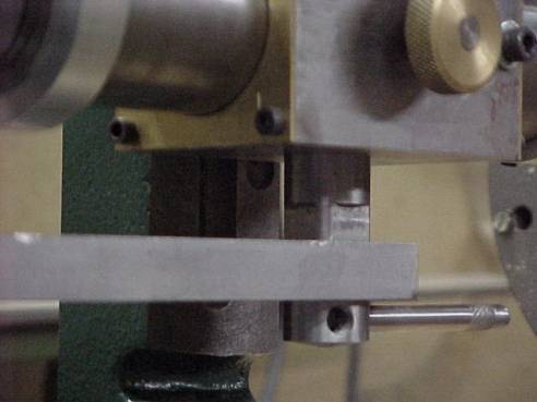
The toolholder reinforcing ring (2) is considered an option. I suppose if the metal at the mouth of the toolholder were thin it might be necessary. By the time I had cut the R8 taper inside the toolholder I had 1/8” wall thickness at the mouth (by design), so a reinforcing ring isn’t really needed. However, I made one out of aluminum with two 10-24 ground setscrews set 120 deg. apart. At the 3rd segment I can screw in (1/4-28) a short piece of 7/16” CRS that rides in the slot of the toothrest bracket (14) so the toolholder can’t rotate during wheel dressing ops. With the little stud removed it acts as a forward stop so I don’t pull the toolholder out of the guide by mistake and have to re-stuff the felt back it.
The pivot shaft (16) was also enlarged to 1” OD. The borings in the castings are made to fit this dimension. Instead of the expensive PGMS that the plans call for, I used plain old CRS, 12L14, finished nice and smooth like the toolholder. Here’s where the second major modification was done. I put a 7/16-20 threaded hole about 1.5” deep in the left end instead of the little threaded stub called for in the plans. The V-groove at the right half is deep enough to make the width of the groove about ¼” so the key (19) will fit nicely but still tighten up when the lockscrew is bottomed out. The right end is faced smooth, no hole.
The end cap (17) is just that. Instead of the plug that goes INTO the base casting, I made a plate of brass, 2” OD by ¼” thick, that is attached ONTO the end of the base casting with 3 equally spaced 10-32 SHCS’s. In the center of the disk is a 1-1/4” long piece of 7/16-20 threaded rod (actually a cut off bolt) sliver soldered in place and faced off smooth. Accuracy counts here because the pivot shaft has to be able to move along this rod as well as inside the casting without sticking or binding. I went this route for only one reason: so I could use the 20 tpi threads for accurate movement of the standard casting with the shaft. The plans call for a 5/16-24 thread at this end, but this means a 24 tpi thread will give .0417” of movement for each complete shaft rotation. The 40 divisions called for in the plans on the graduated dial (25) means each division is .001042” of movement. Plenty close enough to .001”. BUT…..if you want EXACTLY .001”/div. Use a 20 tpi thread, which gives .05”/revolution. Divide the dial into 50 equal parts and each division is exactly .001”. The closest size for 20 tpi threads is 7/16-20, hence the enlargement of everything. Also, the plate instead of the plug gives a wider range of movement of the standard casting.
Extension arm (23) is pretty straightforward rotary table work. No surprises here.
The foot casting (6) and the standard casting (7) can be worked as a pair to start. The castings come completely rough, no holes or machined surfaces, only a partial slot cast in. I started out putting these in the vise on the vertical mill, as level as could be done, and smoothed off the top surface. (Remember to make the first cut on cast iron deep enough to get through the surface layer. The rest of the cuts go much smoother). The casting was flipped over, into the vise on parallels, and worked on the bottom until the 1-1/8” thickness was reached. This leaves maximum thickness at the slot. The slots were then milled out as follows: on the foot casting a ½” 2-flute end mill was used to get the ½” slot. On the standard casting I started with a 7/16 2-flute mill then gradually brought the width up to a nice sliding fit on the flanged slide (9) using a 7/16 4-flute mill. It finished out at just under ½”. I then turned the castings sideways and indicated on the milled slot to get the ends parallel with the slot and the bored holes perpendicular to it. This is also somewhat critical, as it affects alignment of the machine. The holes were started at ½”, then ¾”, then 7/8” with a long 7/8” end mill to insure straightness. Both castings were then bolted to the boring table the way they would fit together, indicated on the slot, and line bored together. A light honing and the shaft is a perfect fit. Other surfaces were machined and holes drilled according to the plans. Don’t forget the 1/16×3/8 slot and tapped holes for the safety lock on the standard casting. The unmachined surfaces were then primed and given 2 coats of Hunter Green spray paint. I figured Battleship Gray looked too “heavy machinery” for this. Black would probably look good, but green looks more to me like “precision machinery”. Whatever.
The graduated dial (25) was alluded to earlier and is made pretty much according to the plans except 1) it’s bored out to fit the 1” shaft; 2) it’s divided, on the spin indexer like the other dials, into 50 divisions; and 3) it’s held to the pivot shaft with two 10-24 setscrews set 90 deg. apart. No need to grind these setscrews as the installation is permanent.
The safety lock (26) can look any way you want it to, so long as it works.
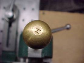
The Guide and Standard Clamp Screws can be alike or different. I tried using ball-handled lock screws for both, but it only works out on the standard casting (holding the guide through the flanged slide). The base screw hit the grinder as it was turned so I changed that one to a screw similar to the toothrest bracket/guide clampscrew (#24). This allowed me to turn the nut down by hand then screw in a handle for the final tightening. Could’ve done the same for the other screw but I had too much fun making the double ball-handled screws that I had to use at least one of them.
Setting gauge (12)….done as per the plans. One for straight flute cutters and one for helical flute cutters. Pressed a 5/8” D brass ball on the top of each one for safety.
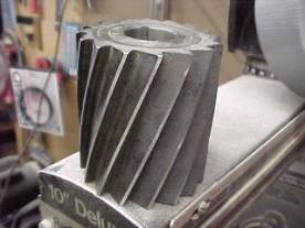
Miscellaneous parts: screws that hold in small parts, like the safety lock, setting gauge, and toothrest finger are just socket-head cap screws pressed into a through drilled and knurled brass head, 5/8” D, with the socket head showing in case the screw needs to be cranked down with an allen wrench. Pointers are scraps of brass from the guide’s end plates. All screw holes are filled with either a working screw or a dummy screw acting as a dust plug to keep out grinding grit. Also made a holder for a 3/8” D diamond dressing tool used in conjunction with the reinforcing ring/stub assembly (other end fits a ½” collet), and a holder for shell mills and plain mills up to 3” long and 2-1/2”D that fits a ¾” collet. The toothrest bracket has to sit further below the guide for the larger diameter cutters, so some “screw extenders” were made in varying lengths so that the toothrest could be used. Might make the rotary table for it, but I sharpen my lathe tools on a different grinder so maybe not. Probably won’t make the reamer grinding attachment either. Once you sharpen a reamer, you change it’s diameter, however slight, so I’ll just buy new ones as needed (every 50 years or so).
That’s about it. As I said, these are just my notes taken as I built this tool. Maybe there’s some stuff here someone else can use. It was a fun project that didn’t take too long (compared to making a Quorn, I’m told), and it does a real nice job of sharpening those expensive milling cutters.
2003 Notes:
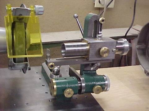
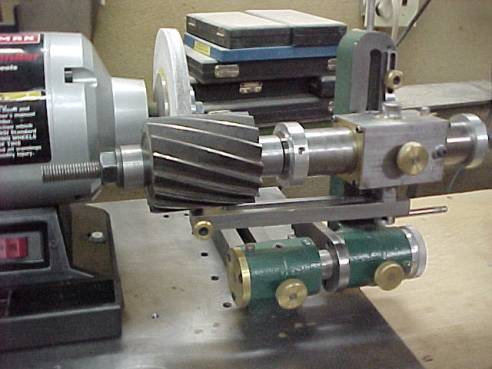
- Notice to all: Some of the following pictures show my setup without a guard on the grinder. I removed it because it was in the way. If I get hurt, that’s my problem, as I’ve been warned. Do like I say and not like I do: keep the guard on the freakin’ machine!
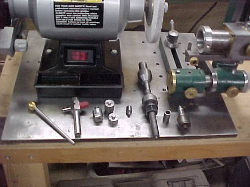
- The air-bearing adapter business didn’t work out too well. So, even though it’s in the picture, I never use it. Doesn’t mean it won’t work for you, I did it as an afterthought.


Author: Bob Darin – Lewiston, NY – © 2002,2003
